Monday, April 29, 2013

Camper Upgrades

Last summer we (My wife and I) purchased a used Starcraft 1701 pop-up camper.  The camper was in excellent shape, but RV construction in general is not top quality and to add to any existing shortcomings, we camp in undeveloped areas with no electrical or water hookups.  I knew this going into our first trip and planned accordingly, which included bringing a notepad to document things I didn't like and plan upgrades for later. (FUN!)

As a result, I ended up with a healthy list of action items, but at the top of the list was solar power to keep the battery charged and the furnace running during cold nights in the mountains.  Working both ends of the power problem,  I decided to replace the wasteful interior lighting with more efficient LED lights.  

After the second trip, I discovered some serious design flaws in the plumbing of the water tank and pressure pump.  While traveling down a back road, I looked in the mirror and caught a glimpse of water trickling from the underside of the camper.  Upon opening the camper, I discovered a small lake on the floor.  A quick inspection brought to light that the water tank was not bolted down and the water pump was plumbed with hard lines.  As the tank bounced up and down, it slowly unscrewed the pump fittings until water began leaking everywhere.  In addition, the pump was a low-end model SureFlo on/off style pump with no pressure accumulator.  The end result was a pump that cycles on and off very quickly at low flow rates, which is common for us since we try to conserve water while camping.


Starting with the easy upgrade, I ordered a pair of LED replacements for the interior dome lights from Amazon.com.  My wife really appreciates the glow of an incandescent bulb, so I made sure to purchase LEDs with a color temp in the 2500-2700K range.  Unfortunately the documentation in the owners manual was about as good as the design of the plumbing system.  When I went to install the bulbs, I discovered that socket in the fixtures did not match what the manual stated it should be.  Frustrated and not wanting to wait for new bulbs to show up, I permanently mounted and wired the new bulbs to the existing socket.  This was done in a way that can be reversed later if I desire.


The color is spot on and with the covers installed, I doubt anyone would notice the difference in bulbs.


At the end of last season I had pulled the tank and old pump to winterize the camper.  The new pump is a SureFlo Extreme series smart sensor.  It utilizes an on-board pressure transducer and microcontroller to vary the speed of the pump to compensate for changing flow rates.  The end result is a pump that is more quiet, smoother, and does not require a pressure accumulator to operate properly.


I installed the pump with Anderson Powerpole connectors to make for easy removal during the off-season.  A new shutoff valve was installed and soft lines run to/from the pump to isolate vibrations and excess movement.  A bracket was added (not shown) to hold the tank down and prevent shifting.


Last was the solar system.  I was most excited about this since I have yet to finish my larger system at home.  The solar for the camper was to be a budget system, so I sourced 2 panels from Craigslist that had been decommissioned from a roadside construction sign.  The panels were dirty, but of good quality mono-crystalline construction and 110 watts each.  I purchased a PWM 20amp 3-stage charge controller from Morningstar.  This unit also had load control, which I may or may not use.

I decided to make the system modular and portable for two reasons.  1) Mounting the panels to the roof of the camper would not work very well for our situation because we tend to camp in the trees, which shade the camper.  2) I want to be able to use this system for other purposes, so portability would be a plus.

I wired each panel with its own Anderson connector and enough wire to reach out of the trees into direct sunlight.  This allows me to use one or both panels depending on my power needs.  


The charge controller was also wired with Anderson connectors and, for now, I used alligator clips to connect the battery, but I will install more connectors on the camper to ease hooking up the panels later.  


System performance was excellent.  The maximum amperage the panels can generate is about 13A.  At 5:00pm I was still seeing 9 amps being delivered to the battery and at sundown, the panels were still producing enough power that the charge light was lite on the charge controller.  220 watts is far more power than I need right now, but I plan to add an additional battery to the camper later and that will allow me to run some additional loads while camping.  If I ever run the battery down too far, the charge controller can recover a battery that has been discharged as low as 1V.   

Post-trip update:
I had ordered LED replacement bulbs for the running lights prior to our latest trip.  To my surprise, they showed up within 36hrs, so I quickly installed them before hitting the road. 
Before:

After:


Not a large difference, but the light is more crisp and the LEDs will last a long long time, while withstanding vibration better.


The solar system worked excellent.  I wish I could have gathered more data, but the weather was very mild and we did not consume much power during the night.  As a result, the battery was topped off and charging in Float mode by 9am the first morning.


I did discover that finding my way in the camper after dark was difficult without turning on the dome lights and waking up my son. (He's 2yrs old).  After returning home, I spotted some LED strip lights at Walmart that are normally used as accent lights on vehicles.  They had a white set that could be cut to length for relatively little money.  I mounted them under the edge of the cabinet adjacent to the walk way and wired it to full time power via a small toggle switch.


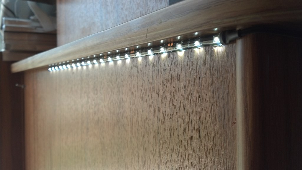
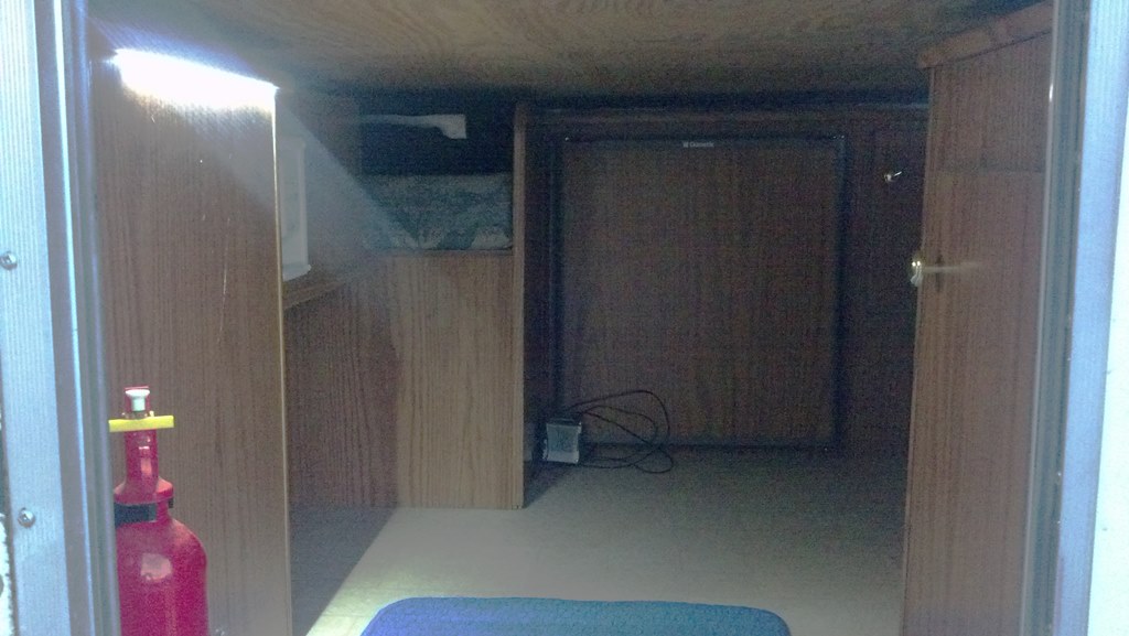
The end result works very nice.  I can see what I'm doing without disturbing others in the camper and as a bonus, the lights allow me to see when I crawl in the camper while its in travel mode.


The last item of business was the fridge.  While camping, the propane burner kept blowing out and I restarted it at least 18 times.  Lucky for me, my friend suggested I check and possibly clean the burner when I get home.  It turned out he was dead right.  Although a little difficult to see, there is what was left of a spider in the burner tube disrupting the air flow.  This was evidenced by the tinge of yellow in the flame.


A little poking with safety wire and flushing with brake cleaner and I had a functional burner again with a perfectly blue flame. 


Not being familar with 3-way fridge performance, I fired up the fridge and monitored the interior temperature drop.  With an ambient temp of 70°F, the fridge took about 3.5hrs to reach 35°F.  Performance may be improved with interior and exterior fans to facilitate air movement, but that is a project for later.

Monday, March 4, 2013

GLCD Automotive Digital Gauge

After years of using aftermarket mechanical gauges in my truck (and repairing them several times) it was time to upgrade.  Not missing an opportunity to make something cool, I decided to go digital using a micro-controller and LCD display instead of analog gauges.

Starting off simple, I wrote a test program and wired up a 16x2 alphanumeric display.  The test program showed values for water temperature, oil pressure, Air/Fuel ratio, and battery voltage.


Thinking that I might want to display more parameters like indicators for 4x4, Low Range, and front & rear lockers, I moved the program to a larger 20x4 LCD.


After acquiring a 128x64 graphic LCD display to play with, I wrote a new test program to take advantage of the flexibility of the graphic display, including adding an intro screen with bitmap images.  The monitored parameters were changed slightly.  Displayed were values for water temperature, oil pressure,and voltages for the primary and secondary batteries.


Unfortunately the graphic LCD uses a LOT of I/O pins, including 5 of the 6 analog pins on the ATMega328, which makes it hard to monitor analog sensors.  One way to get around this would be to re-map the I/O pins to free up analog inputs.  Currently data and command pins are group together, each on their own port.  Remapping the pins would spread them across more than one port and slow performance slightly.
Other options include using a second uC to gather the data from the various sensors and pipe the information to the display via the serial UART, or use a analog multiplexing IC.  Depending on the performance penalty, the path of least resistance would appear to be remapping the I/Os.  More experimenting is in order!

Tuesday, February 26, 2013

Logic Analyzer Decoding PPM and TTL Serial

In my spare time I have been teaching myself to program microcontrollers, specifically Atmel ATMega328s & ATTiny85s using the Arduino IDE.  It has been fun learning what can be done with a few lines of code and a handful of $3 ICs.  As a result, it has become necessary to better understand how devices communicate and one of the best ways to do so is with a logic analyzer.  I recently purchased a Saleae Logic 8-channel logic analyzer and went to work testing anything I had lying around.

First up was my Futaba 4 channel RC transmitter. (See this post about converting a Futaba 4 channel radio to 5 channels.)  For those who are unfamiliar with hobby grade radio control equipment, they typically use pulse-position modulation to encode stick inputs and pass the information to the servos.  The transmitter reads the position of all the inputs and encodes this information as a single pulse train as shown below.


To decode this pulse train you have to understand that RC servos are fed a pulse-width modulated signal at 50 hz. Pulse length represents position and varies from 1ms to 2ms with 1.5ms being the neutral position in most cases.  Looking at the pulse train above you can see the signal is held HIGH and the pulled LOW for a brief period. If you measure the time between the falling edges, you will see that it is about 1.50ms and the pattern repeats 5 times.  This is the position of the 5 channels encoded as a series of pulses.  Pretty cool huh?  It should be noted that Futaba uses inverted logic and other radio systems may use a signal that starts LOW and is driven HIGH.


After looking the transmitter's output, I wired the logic analyzer to the receiver and recorded another sample set.


The job of the receiver is demultiplex the PPM signal into the individual servo signals as shown above.  Channels 1-5 show how a PPM signal is usually decoded.  On the first falling edge of the PPM signal, the output for channel 1 goes HIGH, on the next falling edge of the PPM signal, the output for channel 1 goes LOW and the output for channel 2 goes HIGH and the pattern repeats until all 5 channels are decoded, at which time there is a long pause that tells the receiver to start over at channel 1 on the next falling edge.

This is where things stopped making sense.  My 4 (now 5) channel radio came with a 7 channel receiver.  Looking at the 6th channel, it can be seen that it outputs a pulse that goes LOW at the beginning of the PPM train and then HIGH again at the end.  This isn't useful for driving a servo, so I'm not sure if it was ever meant to serve a function.  Channel 7 mimics Channel 1 and Channel 8 does nothing, which confirms that it is simply a battery input.


Next I wanted to test the actual logic analyzing functions of the software.  I wired a graphic LCD to an Arduino and loaded a sample sketch that reads data from the serial UART and displays it on the screen.


Typing a simple "Hello World" in the serial monitor window, I hit enter, sending the information to the Arduino and the logic analyzer.


I added an 8N1, 9600 baud analyzer to Channel 0 and, as seen above, it decoded my "Hello World" comment also showing the 'n/' newline escape sequence at the end of the string.

So far I'm impressed at how easy this unit has been to operate and hope to put it to use in the future.

Monday, February 18, 2013

Off Grid Solar Generator - Part 2: Battery Packs

Starting from the ground up, I decided to build the battery packs first.  Needing to split up the weight so that the system will remain man portable, the batteries were split into two series wired 12V packs.  I also took this opportunity to upgrade the wire size, add fuse protection, and seal the batteries to make it possible later to add hydrogen ventilation.

To begin, the framework was divided into two smaller frames that fit tighter around the batteries.


Then trays were cut to support the batteries using aluminum sheet.  Holes were cut into the sheets and then dimple die'd to add rigidity.


 A 200 amp Class T fuse was added to each pack for short-circuit protection and mounted in an accessible location.


Installation instructions for the PROsine inverter recommend 250 MCM battery cables for runs under 6ft.  Two battery packs means two wire runs, so wire size can be reduced significantly.  Looking at ampacity guidelines, two runs of 1/0 cable has an ampacity 20% greater than a single run of 250 MCM cable.  Wanting to achieve good crimps, I made a test crimp with a new homemade tool,then cut the cable lug in half.  The results were good, the copper was solid and tight within the connector.


The 1/0 cable was cut to length, then lugs were crimped on and finished with heat shrink tubing.


Here is the pack wired up and terminated with an Anderson SB175 connector.


To finish each pack, plastic panels were cut to (semi) seal up each box.


Up next: Part 3: The inverter/charger module

Friday, February 8, 2013

Off Grid Solar Generator - Part 1: Parts and Testing

A solar generator is a handy item to have for power outages, remote backwoods camping, an off grid cabin, or perhaps the zombie apocalypse.  There are many pre-packaged options, but where is the fun in that?  

By doing some data gathering, calculating and experimentation, I concluded my base emergency loads in the house total 2400 Wh/day, with occasional additional loads for charging batteries, running computers, etc.  Loads for camping are considerably less.  Running wattage for my furnace (assuming the gas is still flowing) is fairly low, but wattage could exceed 1200 W during the startup cycle when the ignitor is on.  With that in mind I chose a Xantrex PROsine 2.0 inverter.  


The PROsine is a 2000 watt continuous pure sine wave unit.  It has a 4500 watt surge capacity, which is much better than the 2500 watt surge you typically see with a 2000 watt gas generator.  This inverter has enough oomph to start my 2HP air compressor (6HP surge).  In addition to its inverter functions, the PROsine has a built-in 100amp, 3-stage battery charger with equalizing ability and an AC transfer relay.  I chose the 12VDC model to maintain compatibility with my vehicles and other 12V accessories.


I ran the PROsine for a few years with a pair of marine deep cycle batteries I had lying around.  Their performance was adequate, but nothing to brag about.  When the time came to upgrade batteries, I looked at my budget, then purchased four 6V golf cart batteries from Sam's Club.  Golf cart batteries tend to be good performers at a fair price for people starting out in alternative energy.  My new batteries, wired in a series/parallel configuration, provide 440Ah @ 12VDC.  With most of the budget spent on batteries, I was stuck with the original 4ga cables I used with the marine deep cycles.  With an inverter the size of the PROsine, 250 MCM is usually the recommended minimum.


Taking measurements with a digital multi-meter I discovered i was losing about 0.5VDC in the cables at 20 amps DC. This severely limits the potential of the inverter at higher power levels and starting inductive loads, such as electric motors.

Up until this point, I was running the inverter as a fancy UPS device.  With a little more money in the budget this year, it was time to add the last components to finish building a true solar generator.  Shopping around, I was surprised to discover how low solar panel prices had gotten if you were willing to buy larger panels.  

I purchased three 255watt SolarWorld mono-crystaline panels and a Outback FlexMax 80 solar charge controller.  Mono-crystaline panels have good conversion efficiency (15%-17% percent) compared to their amorphous counterpart, therefore requiring about half the square footage, a bonus when hauling panels into the field.  The FlexMax 80 is a MPPT type charge controller, which has two key advantages, 1) Maximum power point tracking allows for more power to be harvested from the panels compared to a simple Pulse Width Modulated charge controller.  Conversion efficiencies are 95%-98% compared to 60%-70% for PWM controllers.  With solar still an expensive option, getting as much power as possible from your panels is important.  2) Being a MPPT type charge controller, you can wire your solar panels in a series configuration and utilize higher transmission voltages between the panels and the charge controller, resulting in lower line losses and/or smaller wires.

Since this system was to be semi man-portable, I wanted to split the 4 batteries into two separate battery "packs".  With that in mind, I also ordered a handful of battery terminals, 1/0 cable, and Anderson SB175 connectors.  SB175 connectors are typically used as high-amperage plugs for vehicle accessories such as winches, jumper cables, portable welders and inverters.  At full running wattage, the inverter will be drawing around 200 amps @ 12V, factoring in conversion efficiencies.  Since I will be running one connector on each battery pack, my total continuous rated amperage through the plugs would be 350 amps with considerably greater surge capacity.

Before going any further, it was time to rough wire the components together and test them out before any further construction.  I wired the charge controller to the batteries and set the panels outside.


Open circuit voltage was just below the rated OcV, but this was late in the day and the sun was falling fast.  I ran the cables back to the charge controller, checked the polarity and plugged them in.  The running voltage dropped to 107.5 VDC from 130 V open circuit.


I then watched the display on the charge controller and monitored the output to the batteries.  Unfortunately with the sun going down I was losing about 7 volts/min from the solar panels.  It didn't take long to drop to 70 VDC on the input, but the system was working as it should.


With everything working it was now time to turn focus to the mounting and wiring of the components.  In Part 2 I will show how the battery packs were constructed and wired.

Saturday, January 26, 2013

Futaba Sky Sport 5-Channel Upgrade

The Futaba Sky Sport Radio has been around for a number of years in various forms and versions.  I purchased one in 2005.  It always bugged me that opposite the trainer switch was a plastic plug that looked like there should be another switch.


One day out of curiosity, I took it apart and began to study the circuit board.  In most radios, there is a multiplexing chip that reads the state of the various inputs and converts it to a PPM serial stream that is fed to the RF unit.  The receiver then decodes this pulse train and uses it to signal the individual servos.  Following the wires from the joystick pots to where they attached to the board (shown in RED below), and then the traces on the board, I figured out which IC was the multiplexer. (shown in BLUE)  After some internet searching and following the other traces feeding into and out of the IC, I found three unused solder pads on the board. (shown in GREEN)  Two were 0V and +5V and the third went back to the multiplexer.  I thought, "It can't be that simple."  I soldered in a 5th pot and wired it to the spare solder pads.


To my surprise it was just that easy!  Why the radio was not built this way, I don't know.  It even came with a 7-channel receiver and I am not a aware of a factory 5 channel version that would have been built on the same framework. 

Wednesday, January 23, 2013

The Tiny Wheel Trinket

A friend of mine, who makes jewelry, recently laid down a challenge for me to create something "crafty".  Being an engineer, I am anything but artsy, but I gave it some thought and after a few hours playing on the mill I came up with this:


It was suppose to be tiny wheel, but my first attempt did not turn out so well.  As you can likely see from the photo above, while doing the various machining ops, I lost my zero on the DRO and when I went to drill the center bore and lug hole pattern, they were off center.  In addtion, the center bore was too big and the lug pattern ran into it due to the flex in the drill bit I was using.  So I punched out the whole center and chocked it up to a learning experience.

Discourage my mill lost its zero and knowing that I could not sleep well without figuring out why, I headed back to the garage around 10:00pm.  It didn't take long to conclude that the likely culpirt was a loose gib on the X-axis.  (The Y maintains a perfect zero.)  After some adjustment, I was up and running again.  Now encourage, I pressed forward with a second attempt at producing a miniature wheel.  This time I drilled the lug holes first using a center drill to lay out the pattern followed by drilling the hub bore after double checking that I was still on center.  This worked much better aside from the 1/16" bit snapping off in one of the holes.


My second attempt still needs polishing, but it turned out much better than the original and makes a cool desk trinket.  I was even able to punch out the broken drill bit after milling the backside counterbore.


Update 1/28/13:  I finished a few more to hand out to some friends and one made from aluminum which turned out nice.

New Tools And A Bracket

In my never-ending quest to expand what I can fabricate, I purchased a set of SPC / Light Racing flared hole dies.  I got a good price on these and as a bonus, they are also highly engineered, using Finite Element Analysis to optimize the angle and radius of the die in order to achieve the maximum depth of flare without cracking the base material.


My first experiment was with a very thin piece of aluminum sheet I had laying around.  I cut holes in it for all 5 sizes of dies I purchased and used a hydraulic shop press to create the flares.


There's not much to it, but these are great for adding bending and compressive strength to sheet metal pieces.  


My other tool is a battery lug crimper I made for an upcoming solar project.  (More on that later!)  This was a quick test to see if it was possible to achieve a good crimp with minimal time invested.


Sadly this worked, but not as well as I hoped.  The lug is crimped tightly, but the tool cuts into the lug if clamped too hard.  I will try again later when I have more time.


And finally, I received a new Ham radio for Christmas with APRS capability!! (A Yaesu FTM-350ar to be exact.)  But the suction cup mount that came with the head unit absolutely sucks.  It's so bad they give you an adhesive doughnut to stick to your dash because the suction cup can't stick to anything on its own.  Well this just was not going to cut it, so I whipped out a bracket to mount the head unit to the dash via the un-used ash tray.


I'm not sure if I'll leave it here permanently, but it works well and it is easy to push the buttons with my fore finger while shifting gears.